Quiz Buzzer
Published by Arun Isaac on
Tags: electronics, project
This version of the buzzer has been superseded by the Quiz Buzzer v2.
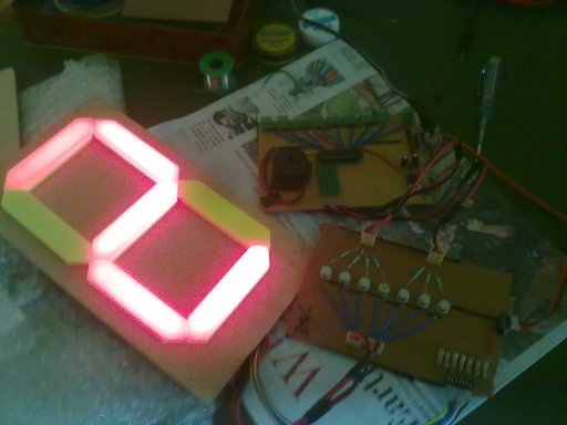
Figure 1: Quiz Buzzer – PCB with LED Display
This is a quiz buzzer system supporting a maximum of 8 teams. It uses an ATMega8 microcontroller unit to continuously read the state of the buzzer switches, find which team pressed the buzzer first, and display the appropriate number in the seven segment display. Once a buzzer press has been detected, the program on the microcontroller latches on to that team no, and will not respond to any other buzzer presses. This state can be reset by using the RESET switch.
A simple CL100 driver circuit was used to drive the seven segment display. Power supply used was a 9 V 1 A source. The 9 V source was directly used as Vcc for the CL100 driver circuit. A 5 V 7805 regulator was used to regulate the 9 V to 5 V and provide Vcc to the microcontroller.
Basically, Hari (Hari being a particularly involved ASQ member) decided to build this buzzer for the ASQ (Association of Serious Quizzers) in our college. The ASQ did not own a buzzer, the buzzer rent was unreasonable, and basically it just didn't make sense for an association of quizzing engineers to not have a buzzer of their own design.
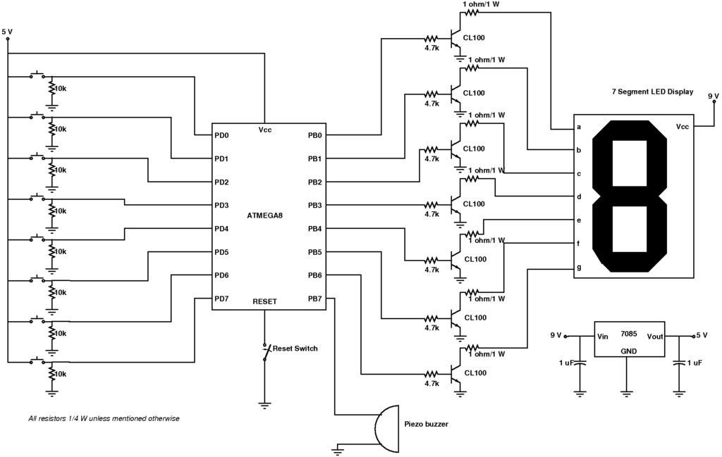
Figure 2: Quiz Buzzer – Schematic
Hari started out with a combinational logic design with latches, encoders, code converters and the lot. The plan was abandoned due to the tedious wiring involved. And what with the Kriya 2011 time crunch approaching, I suggested he go with an AVR microcontroller based design. And, together, we sat down one night of the semester exams, finished the program and tested a miniature breadboard version of the buzzer.
After lots of shopping and research, the buzzer switches, long wires, seven segment displays, and all the other components required for the buzzer were rounded up. As usual, Hari being a demanding consumer, and a perfectionist (sometimes a maniac of a perfectionist) had to do all his research. And after three sleepless nights of soldering on Hari's part with Nishanth toiling to keep up with Hari's standards, the buzzer was at last done. A few hiccups with the design here and there, with Sudhakar coming in to save the day and all, but in the end, things turned out fine and I'm happy for that. :-)
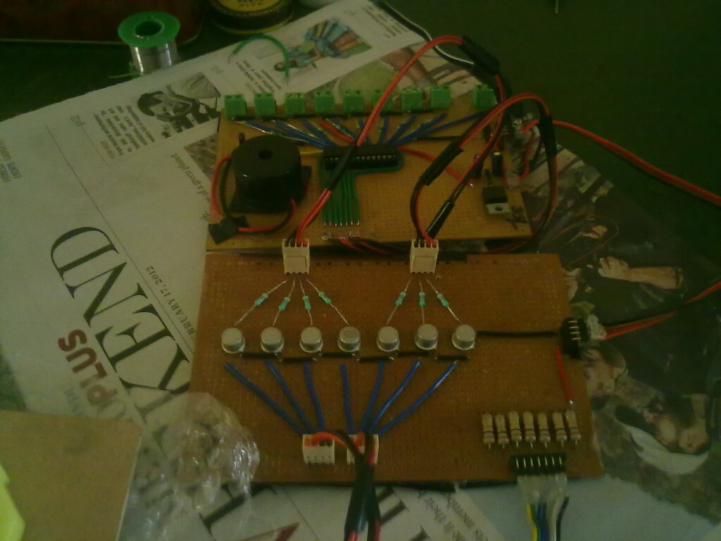
Figure 3: Quiz Buzzer – PCB
<iframe class="youtube-player" type="text/html" width="640" height="385" src="https://www.youtube.com/embed/5NIEifqPkQA" frameborder="0"> </iframe>
 All content is licensed under a