Quiz Buzzer v2
Published by Arun Isaac on
Tags: electronics, project
Downloads
- quizbuzzerv2_manual.pdf - User manual
- quizbuzzerv2.zip - Hardware design files, firmware source code, documentation, and everything else to do with the buzzer
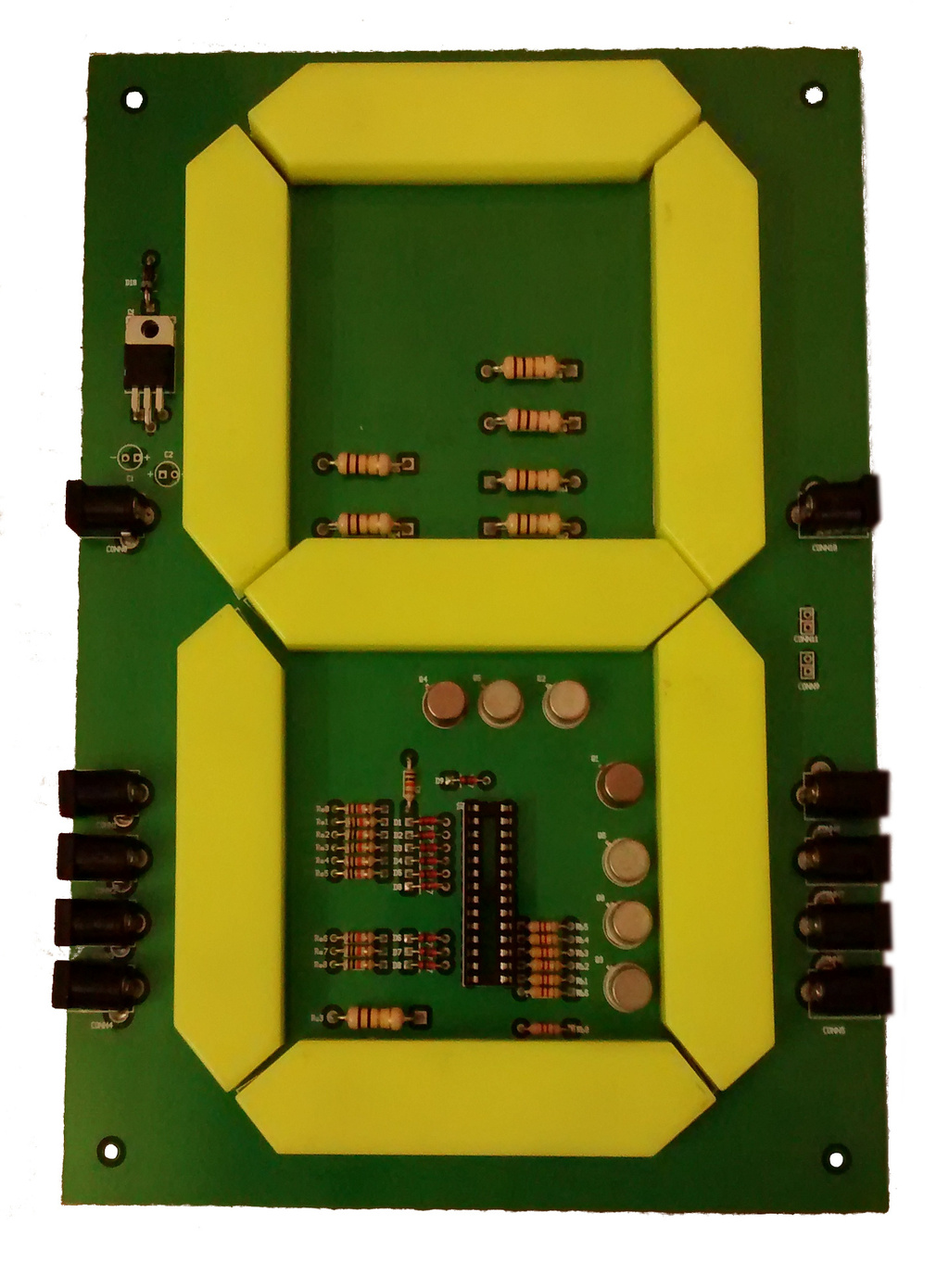
Figure 1: Quiz Buzzer v2
After being stuck in development hell for a few years now, version 2 of the Quiz Buzzer is at last here. With Hari and I finishing our Bachelor's, and Hari taking up his job in Caterpillar, and me settling into my Master's at IISc, Bengaluru, time has been hard to come by. This version of the quiz buzzer has been in use by the ASQ (Association of Serious Quizzers), PSG Tech, Coimbatore for more than a year now, but the final iteration of polishing/testing/reengineering had to be done. And, I'm happy to say that the buzzer is now complete, at last!
The original buzzer began as little more than a personal project to get rid of ASQ's dependence on expensive rented buzzers. It was possibly the first useful thing that we made, and in that sense, it was a success. But, back then, we did not know how to design and fabricate PCBs, and we naively believed that perforated boards were sufficient. Also, I (Hari, not so much) kinda underestimated the human usability and non-technical design elements of the buzzer.
A lot has changed since that time. Our technical know how has greatly increased. We have worked on several other projects, and gained a lot of experience. We can now wield a lot more hardware/software tools. And, of course, we are no longer teenagers (nothing wrong with being a teenager - just that you are a little cocky and no one takes you very seriously)! The redesigned and rethought buzzer is a culmination of all this. So, enough stories! Let's get to the point.
The new buzzer is one single all in one board with the LED seven segment display, the display driver circuitry and the controller circuitry all integrated into one "monolithic" PCB. This greatly cuts down on the number of connectors involved and the mess and confusion related to all the various interconnecting wires going back and forth.
The LED driver is still the same CL100 transistor circuitry. One nagging fact is that it is an open loop design. Therefore, it is sensitive to variations in the transistor and LED parameters. So, in order to get better control of the LED current, PWM (pulse width modulation) of the LED pins has been implemented in the firmware. When I designed this driver circuitry, I didn't know about the ULN2003 Darlignton array. If I were to design a new buzzer, I'd probably use that.
The long wires (length of 10 m) connecting the team switches to the buzzer board were picking up electric noise and triggering the microcontroller even without any switch press. We tried a ferrite bead, and it was able to suppress the noise, but then decided to go for the pure software solution of repeatedly sampling the switch pin, and making sure it was a true switch press, and not some random noise picked up from somewhere. The repeated sampling technique worked quite well. We actually tested it by switching a ceiling fan on and off for a hundred times, and it didn't suffer a noise trigger in even one of those hundred trials.
The switch and power ports used in the buzzer are all standard 2.1 mm DC connectors. It is quite easy to accidentally plug in the power adapter into one of the switch ports and end up damaging the microcontroller. In order to protect against these, diode networks have been placed in front of all the switch pins. The diode networks have been tested, and work fascinatingly well.
The power adapter used by the buzzer is a 9 V 2 A DC adapter. The buzzer requires a maximum of only around 1 A of current. But, these cheap supposedly 1 A SMPS supplies that we commonly get on the market don't seem to live up to their ratings. So, in order to be on the safer side, it is better to use 2 A supplies and operate well within the maximum ratings.
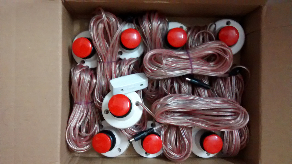
Figure 2: Quiz Buzzer v2 – team and quiz master reset switches
The first shipment of the buzzer went out only a couple of days back. Gokul pitched in at the last moment, and helped us in formatting and getting a printed copy of the GPLv3 (General Public License) ready for shipping. We also made a nice user manual using asciidoc. Many thanks is also due to Sudhakar who very painstakingly routed the buzzer PCB to my exacting (and sometimes unreasonable) specifications. That fellow has a rare gift for patience and tolerance (sometimes, too much tolerance!). Also, thanks to Arijit, for making me believe once more that physics works!
As usual, all designs are open. The hardware designs and the manual are under a Creative Commons Attribution-ShareAlike 4.0 International License. The firmware is free software distributed under GPLv3. Download links are at the top of the page.
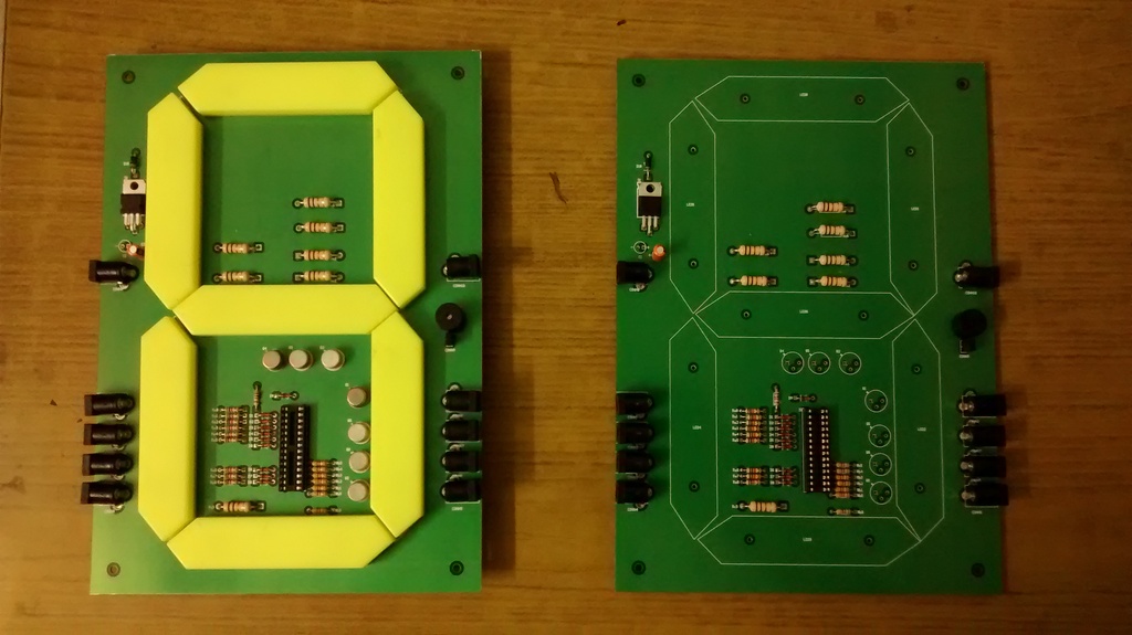
Figure 3: Quiz Buzzer v2 – two side by side
 All content is licensed under a